
The Zener diode is distinguished from other semiconductor components by a parameter that is often misunderstood: its reverse breakdown voltage is not an absolute value. It depends on the test current specified in the manufacturer’s datasheet. Understanding this nuance changes the way to size a regulation or protection circuit and avoids output voltage discrepancies that many designers discover too late on their prototype.
Zener Voltage and Test Current: What the Datasheet Really Requires
Most datasheets indicate a nominal Zener voltage associated with a specific test current. This pair of values defines the guaranteed operating point. Outside of this point, the voltage across the component varies.
Two complementary parameters deserve careful reading: the minimum regulation current (often noted Izk) and the dynamic resistance (rz). When the current flowing through the Zener drops below Izk, the output voltage falls, and regulation is no longer ensured. The dynamic resistance quantifies the voltage variation for a given current variation: the lower it is, the more stable the regulation.
An article detailing the operation of the Zener diode reminds us that neglecting these parameters leads to sizing a circuit around a theoretical voltage that does not correspond to the actual behavior of the component under load.
| Parameter | Role | Consequence if Ignored |
|---|---|---|
| Vz (nominal Zener voltage) | Reference voltage at test current Iz | Output different from the expected value if Iz is not respected |
| Iz (test current) | Guaranteed operating point by the manufacturer | Unstable regulation outside of this point |
| Izk (minimum current) | Threshold below which regulation is lost | Output voltage collapsing under heavy load |
| rz (dynamic resistance) | Sensitivity of Vz to current variations | Output ripples proportional to rz |
| Pz (maximum power) | Thermal energy that the component can dissipate | Destruction of the component due to overheating |
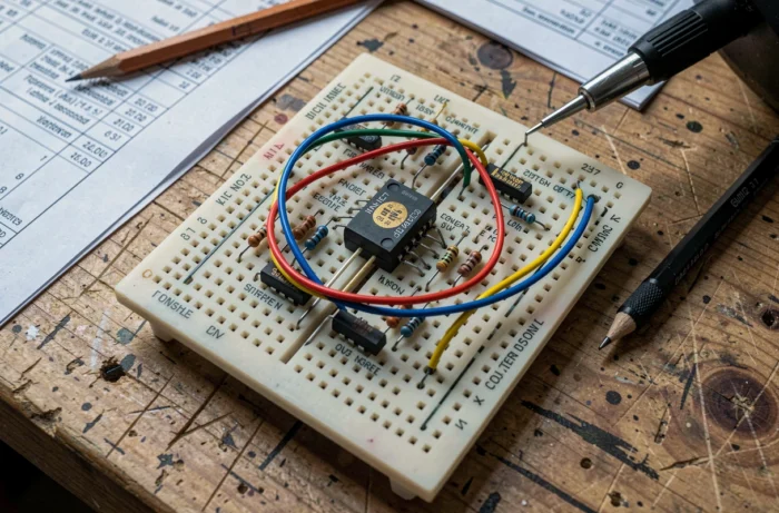
Sizing the Series Resistor: Calculation at Both Operating Extremes
The most common circuit using a Zener diode is the shunt regulator: a series resistor limits the current between the power supply and the Zener, placed in parallel with the load. The temptation is to calculate this resistor at the nominal point and then move on. This approach neglects two critical scenarios.
Case 1: Maximum Input Voltage and Disconnected Load
When the load consumes little or nothing, all the excess current flows through the Zener. If the series resistor is too low, the product of the Zener voltage by this current exceeds the allowable power of the component. The result is overheating, sometimes a silent destruction that only manifests later as a drift in the output voltage.
Case 2: Minimum Input Voltage and Maximum Load
Conversely, when the source provides its lowest voltage and the load draws its maximum current, the remaining current in the Zener may drop below Izk. Regulation disappears, and the output voltage follows the fluctuations of the supply. The circuit loses its primary function.
Checking these two extremes before finalizing the value of the series resistor is the only reliable method to ensure that the circuit operates within its entire usage envelope.
Zener Diode and TVS Diode in Circuit Protection: Two Components, Two Logics
Zener diodes and TVS (Transient Voltage Suppressor) diodes both exploit the reverse breakdown of a semiconductor junction. This relationship creates frequent confusion: using a Zener for regulation to protect a circuit against transient overvoltages, or vice versa.
TVS diodes are designed to absorb very short duration pulses (electrostatic discharges, spikes on a power line). Their internal structure can withstand instantaneous energy much greater than that of a standard Zener. A Zener intended for continuous regulation may not survive an electrostatic discharge of a few microseconds if the energy exceeds its thermal capacity.
- A TVS diode is chosen first by its clamping voltage and its energy absorption per pulse, not by its nominal Zener voltage.
- A regulation Zener is chosen by its nominal voltage, test current, and dynamic resistance for continuous operation.
- Placing a TVS in continuous regulation degrades the accuracy of the output voltage, as these components generally have a higher dynamic resistance and a wider voltage tolerance.

Practical Applications of the Zener Diode in Common Electronic Circuits
Beyond voltage regulation in simple power supplies, the Zener diode is involved in several less obvious configurations.
As a voltage reference, it provides a stable potential at the input of a comparator or operational amplifier. The precision directly depends on the dynamic resistance and thermal stability of the chosen component. For demanding applications (metrology, analog-to-digital conversion), reference integrated circuits like the TL431 offer better stability than a discrete Zener, as they incorporate an internal feedback loop.
In input protection circuits, a Zener placed between a signal and ground clips voltages that exceed the breakdown threshold. This configuration protects sensitive inputs of microcontrollers or sensors against noise signals.
- Shunt regulation in low current power supplies
- Voltage reference for comparators and converters
- Clipping signals to protect logic inputs
- Controlled reverse bias in certain oscillators or signal shaping circuits
Each application imposes a return to the same checks: test current respected, power dissipated calculated at extremes, and adequacy between the component’s tolerance and the precision required by the circuit. A well-chosen Zener remains a reliable and economical component. Poorly sized, it becomes the source of a malfunction that is difficult to diagnose, as the output voltage drifts without the component showing any visible signs of failure.